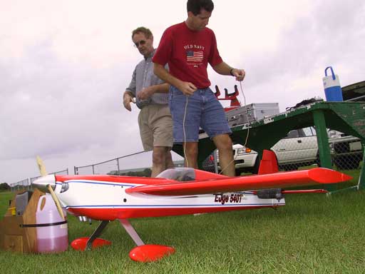
Lanier Edge 540 ARF Review
Mark W. Poole
Specifications
Airplane: Lanier Edge 540 ARF
Manufacturer: Lanier R/C
Construction: Balsa, Lite Ply, Foam
Hardware Included: Everything needed
Wingspan: 73"
Fuselage: 66"
Wing Area: 1008 square inches
Modifications: Canopy attachment, tail wheel
Weight: 11lbs, 10 oz
Wing Loading: 26.5 oz/sq. ft
Recommended Engine Range: .90-1.20
Engine Used: OS 160FX and Bisson Pitts muffler
Hits
Finish of Ultracote covering job and painted areas
Fiberglass cowl and wheel pants
Fantastic Precision and 3D Flight Performance
Misses
Aileron servo wire channel
Back former not relieved sufficiently
Tail Wheel too flimsy
2-56 hardware (should be 4/40)
Introduction
Almost everyone will agree that bigger flies better, but not everyone can afford to go as big as they like or they just don’t have the space to haul a larger airframe. In addition, we all know that ARF’s are filling the bill for many more pilots these days as the availability of free time continues to decrease. Lanier is satisfying the need for an affordable aerobatic ARF that can “fly big” with their ARF Edge 540. The Edge design is well known for its excellent slow-flight and 3D capabilities. Lanier is offering this “big” performance in a quick-building ARF that is convenient in size and much more affordable and manageable than the larger gas-burning monsters.
The Kit
The kit contents are very complete, including the gear, axles, wheels, wheel collars, gas tank, hinges, control horns, and control linkages. The control linkage components are adequate for engines on the low end of the recommended range but I would think that most people would go with something on the upper end and need to replace the hardware with 4/40 components. The Ultracote covering job was great, with no loose ends or exposed areas to be found. A few wrinkles in the Fuselage were easily removed with a heat gun. The cowl and wheel pants are fiberglass and painted to match the Red/White covering scheme. Also included are pressure-sensitive decals for the wings and fuselage sides. I found a couple of areas in the fuselage where more glue needed to be applied. This seems to be a familiar tune with ARF’s from any manufacturer these days. The instructions are well written and include pictures for almost every step of the process. They were the best I’ve seen for any Lanier kit.
Wing Construction
The wings are balsa-sheeted foam with an aluminum wing tube used to mount them to the fuselage. This makes transportation to the field much easier than a single 73” wing. The wings are attached to the fuselage with a socket-head bolt through the top of the wing into the aluminum tube. A hole must be drilled through an embedded dowel in the top of the wing and the wing tube, then tapped to receive the bolt. After attaching the wings I found the incidence of the left wing to be exactly zero with the thrust line and the right wing was at +1/4 degree, pretty close to perfect. The wings come already hinged for the included Robart Hinge Point hinges and were well aligned with the holes in the ailerons. I used 30-minute epoxy in a baby syringe to attach the ailerons to the wings. The aileron mounts are already cut out from the bottom of the wing and have mounting beams installed. There is a channel cut through the wing to run the aileron wires. On my kit, however, this channel had two problems: It wasn’t cut long enough to reach the servo well and it wasn’t aligned in the right direction to have met the servo well even if it had been long enough. I used a coat hanger entered through the servo well to remove foam between the well and the channel. I’ve heard that more recent kits don’t have this servo channel issue. I installed Cirrus CS65 servos and used 4/40 hardware for the aileron connections. Lastly, I installed the pressure sensitive decals to the wings. These really help dress-up the overall appearance.
Tail Feathers
The tail feathers are built-up construction with balsa sheeting and are already drilled for the hinge-points. The stabs are attached to the fuselage with an aluminum tube and can be removable if desired but I opted to epoxy them into place. To keep the tail light, I opted to install a single rudder servo and single elevator servo under the canopy. This turned out to be a good idea because I had to put my receiver battery pack at the very front of the engine box to get the CG at the recommended location. The problem was that the back former wasn’t relieved enough to accommodate the elevator pushrod or rudder pull/pull cables. I opened up the left elevator servo mounting area and used a Dremel sanding wheel to create the clearance I needed. I used a Cirrus CS65 servo connected to a Dave Brown carbon fiber shaft and split 4/40 rods for the elevators, and another CS65 servo for the pull/pull rudder control.
Fuselage Front Hatch/Canopy
The canopy/front hatch area held in place in the front with two dowel rods into the front former, and at the back with two bolts. In the past I’ve seen this type of mount develop a rattle where the dowels insert into the former so I removed them and added two more bolts at the front of the canopy. The clear canopy was well marked for cutting and was attached using RC56 glue. Its an overlap fit on all sides so it mounts very easily. I then used red automotive striping tape to trim the canopy edge all the way around.
Landing Gear
All of the hardware is included for the landing gear, with very lightweight wheels. The gear is held onto the fuselage with two bolts up through a piece of ¼” light ply. I recommend coating the bolt mounting area with some thin CA and use some larger washers on the inside of the fuselage to keep from crushing the wood.
Engine
I chose to use an OS160FX and a Bisson Pitts muffler, wanting a lot of power without excess weight. I’ve heard of others using gas engines on the Edge but I wouldn’t recommend it because of the weight penalty. I mounted the OS on its side using a modified Great Planes adjustable .90-1.20 engine mount. The engine was a little too wide to use the mount at its widest setting so I disconnect the two sides and removed the areas that would have normally been connected, making two separate mounting halves. This makes for a very lightweight mount that has now survived several “very wild” flights. The top of the upper mount half had to have a little material removed (Dremel sanding drum) to keep it from rubbing against the top of the cowl. To give right thrust, I used an Ernst 2-degree thrust plate behind the engine mounts. To give longer flight times, I replaced the fuel tank included in the kit with a 20-ounce tank from Dubro. This required that I enlarge the hole in the front former to accommodate the larger tank, and I installed a sub floor to support the tank on the bottom. The tank rests on a piece of ¼” foam and is held in place with cable-ties. For fueling, I used a Dubro “Fuel It” kit and an extra fill line to the tank. The engine was finished off with a beautiful Tru-Turn spinner and adapter nut for the OS160. The spinner fits fine over the Pro-Zinger props but will need to be cut if a large APC is to be used. The throttle is controlled with a Hitec HS425 servo. A plywood plate is provided to cover the top of the engine box but I chose not to use it. The firewall is certainly strong enough to hold the engine without it.
Cowl
To accommodate the OS160 and Bisson muffler, I used my Dremel to remove a significant amount of fiberglass at the back of the bottom to provide a lot of airflow. The top was relieved to clear the engine head, needle valve, and idle needle. The cowl was then attached to the fuselage with four #4 screws into small pieces of nyrod (not included) glued into the fuselage side. I added two additional mounting blocks on the underside to provide additional support near the cutout areas of the cowl.
Radio
I used a Hitec Supreme 8 FM receiver mounted on Velcro under the canopy, powered by a 5-cell 1500mah nicad pack mounted on the left side of the engine box. This put the CG at the recommended 4 ¾” back from the wing leading edge. The receiver antenna was routed out to the fuselage bottom and held in place using red automotive trim tape. My transmitter is a Futaba 8UAPS set to FM to match the receiver, and programmed to use two different channels (1 and 6) for the aileron servos. This allows me to program flaperons for 3D. Always wanting to try something new, I used an Expert voltage monitor. It’s a small printed circuit board with high-intensity LEDs that indicate the condition of your receiver pack, plugged into an extra receiver port. There are two offered: one for 4-cell packs and one for 5-cell packs and each only cost about 15 bucks. I mounted it on the side of the fuselage just in front of my switch. It is on whenever your switch is on and makes it way too easy to see the condition of your receiver pack. I’ll be using them again.
Preflight
Prior to flying I broke-in the OS160 following the instructions, using 15% Omega fuel, an OS#8 plug, and a Pro-Zinger 18x6 prop. I initially tried to start it with my starter but it wouldn’t turn it over. Using a small piece of 1” PVC pipe, it fired right up on the third flip. It now starts very easily by setting the throttle at a high idle, applying the glow driver, and flipping backwards against compression with my PVC pipe. Initially the engine was running rich in the midrange but it has now cleared up after a gallon of fuel.
I applied the rest of the decals to the Edge but still wanted a few more so I made some using my STIKA vinyl cutter. I’ve never regretting buying it, sharing the cost with another club member. The hard part is deciding when to stop adding graphics to a plane.
Ready to fly the Edge weighed 11lbs, 10 ounces on the scales at my local post office. This was less than any others I had heard of with the same engine. I attribute it to the single elevator servo, Bisson muffler, lightweight engine mount, leaving off the top of the motor box, and not needing any nose-weight as others have indicated doing.
The control throws were set at the recommended settings on low rates, with “all I could get” as the high rates. I also used a significant amount of exponential (60-80%) on the high rate settings, making the plane more manageable around the centers.
Flying
The first flight was performed with the high-speed needle set pretty rich but it was still easy to tell that the OS was going to be way enough engine for the plane. It needed a couple of clicks of aileron to fly level, probably due to the ¼ degree of difference in the wing incidences, and two clicks of down elevator. At the low rates it felt like a pattern plane, very smooth through all attitudes though the elevator was a little too sensitive. After a couple minutes of mid-range flying the OS died and it was time to test the glide path. It glides VERY well and easily made it back to field, actually going too far. A little tweaking on the needle and we were in the air again. The third test flight nearly ended in disaster when the rudder suddenly got stuck with about 15 degrees of right throw. The rough landing cracked the landing gear mount loose. Afterwards we determined that the tail wheel had been rubbing on the bottom of the rudder and eventually grabbed it and locked it in place. The metal arm must have gotten bent on the previous two landings, both of which were very smooth. The tail wheel was certainly not strong enough for the task.
With a new Sullivan tail wheel assembly (S-861) and repaired main gear mount it was time to complete the flight tests. Knife-edge showed a little tuck to the belly on both sides, with a 7-8% mix needed to remove it. The roll coupling was very small, only taking 2-3% mix to remove. The vertical performance is spectacular, easily pulling out of a hover or torque roll with power to spare. The two degrees of right thrust appears to be perfect, as up lines are totally hands-off. On the low rates I went through the IMAC Sportsman sequence several times and felt very comfortable through all maneuvers. At the recommended throws I found the ailerons a little too slow and the elevator a little too sensitive for precision work. Snaps start and stop right now, I undershot the first few I tried, and stalls are dead straight ahead. Knife-edge snaps are very solid. It doesn’t want to keep snapping with rudder applied, as some other planes will do. With 3D rates, upright harriers showed a little wing wagging without any spoileron applied, but it doesn’t get out of control. Rudder easily steered it around. Inverted harriers were dead solid. The Edge does VERY fast, spin-to-a-blur blenders without any signs of fatigue. And once stalled, just a blip of the throttle has it flying again. It also easily does knife-edge loops. Landings can be as slow as you like, just get the nose up and keep a little power to float it on down. After three gallons the OS has yet to flame out since the first day and is really coming on strong. Most flying is done at half throttle.
Summary
This Edge/OS160 combination is a great one. The flight capabilities, weight, and power provide the full range of performance that people are looking for. In a few evenings you have a great entry plane into IMAC flying and one that is also good for learning to fly 3D. The overall size and removable wings make it easy to transport in smaller vehicles, and the construction and covering quality were great. I’ve let several other club members try the sticks and all have said it’s a “fun” airplane. The novices like the low-rate, low-speed stability and the experts like the fact that there’s nothing it can’t do when the rates are turned up.